We have proudly partnered with Benetech to reduce respirable crystalline silica exposure.
Recent regulatory changes to OSHA 1926 CFR-1153(d)(1) have reduced the PEL (permissible exposure limit) to 50 micrograms of respirable crystalline silica per cubic meter of air (ug/m3) averaged over an 8-hour day. The danger of silicosis in workers exposed above the allowable PEL is real and must be addressed. Within the past year, MSHA has also announced new regulations with additional field support to enforce tightening dust control guidelines.
In collaboration with NIOSH (National Institute for Occupational Safety and Health, a division of the CDC), Benetech took the challenge combining their proven products with newly patented technologies to design equipment that would improve personnel safety in the workplace and reduce exposure to RCS (respirable crystalline silica).
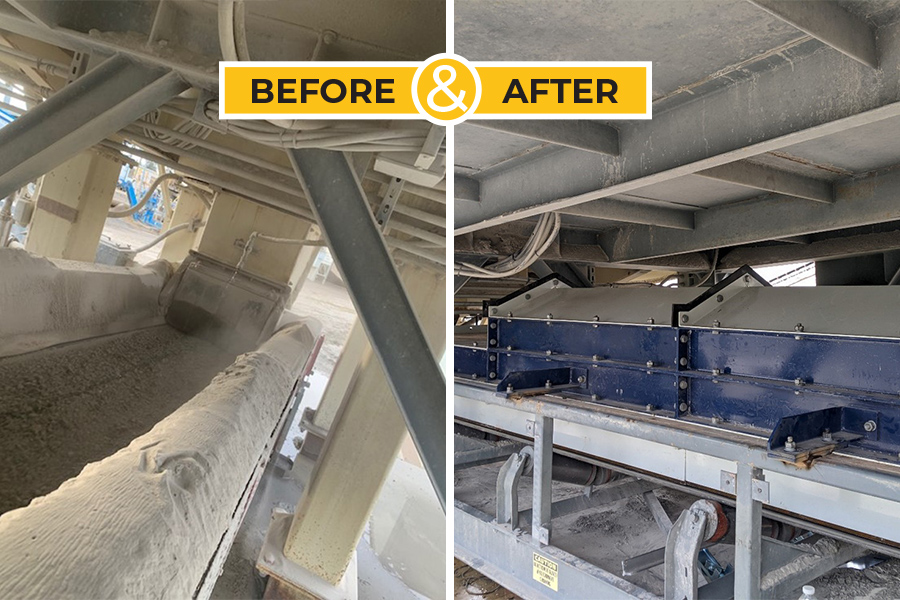
During development of the MaxZone Safe+®, Benetech greatly benefited from NIOSH’s R&D (research & development) team by their documentation of test results showing a significant reduction in dust and spillage at the load zone areas of the conveyor system.
Targeting the load zone area of a bulk material handling system is critical since up to 85% of the dust and spillage occurs in the transfer point and load zone areas. This is also the area where the highest incidence of serious injuries and fatalities occur during routine maintenance and cleanup operations. Personnel exposure to respirable dust is also very high in these areas.
In addition, the economic advantages of this technology allows for minimal use suppression to be employed on an “as needed” basis due to “smart” data communications between devices. And chemical costs can be minimized with an average savings of over 60X when compared to other spray suppression systems available.
Through our partnership with Benetech, we are experts at dust and spillage control, material flow, and production done safely with reduced downtime. Contact us and see how our integrated services and technologies can help improve your operation by reducing dust, preventing spillage, improving material flow, and ensuring compliance.
Sugar Sell, the Intelligence-Driven Sales Automation Solution, Equips Sales with Tools for Improved Productivity and Customer Responsiveness
SAN FRANCISCO – December 17, 2024 – LGG Industrial, a longstanding leader in fluid handling, sealing, and material conveyance solutions, is driving efficiency and growth with SugarCRM’s flagship sales automation solution, Sugar Sell, built to meet the unique needs of business-to-business (B2B) industrial companies.
LGG Industrial offers comprehensive engineered fluid handling, sealing, and material conveyance solutions for a wide variety of industries and applications. With facilities across North America and decades of trusted experience, LGG Industrial is a top solution partner for some of the largest companies in North America.
Over 150 LGG Industrial sales and service professionals are now using Sugar Sell, and the company plans to deploy additional Sugar solutions, including Sugar Serve and Sugar Market, in the near future. The transition to Sugar’s intelligence-driven sales automation platform has transformed its sales operations, equipping sales reps with the tools needed to be more productive, efficient, and customer-focused.
“We chose the Sugar platform because it provides the sophisticated CRM tools we need to execute our new go-to-market strategy and drive organic growth,” said Tim Billingsley, Vice President, Revenue Operations, LGG Industrial. He explains that Sugar Sell has given the company a platform to transform its sales operations, ushering in newfound visibility and efficiency.
“We are looking to Sugar to help us accelerate the velocity of sales opportunities through the buyer journey to realize revenue faster,” added Billingsley. “Sugar is the ideal solution for B2B midmarket businesses like ours, and it’s a perfect fit to help us scale our sales operations and drive more revenue. With the introduction of Sugar Sell, the company has experienced 3 times the user adoption of previous sales tools.”
Sugar will also help the company better manage and respond to spikes in customer demand due to extreme weather and natural disasters.
“Helping LGG Industrial meet its unique business needs and overcome industry-specific challenges is a core strength of our CRM platform and a key area of expertise for our team at Sugar,” said Paul Farrell, Chief Product Officer, SugarCRM. “Creating new sales opportunities, expanding pipeline, accelerating sales processes, and driving faster revenue realization are key goals for LGG Industrial, and we’re pleased to be the solution to help the company achieve these goals and more.”
Click here to learn more about Sugar’s AI-driven solutions for CRM.
About SugarCRM
SugarCRM is a CRM software that helps marketing, sales, and service teams reach peak efficiency through better automation, data, and intelligence so they can achieve a real-time, reliable view of each customer. Sugar’s platform provides leading technology in the sales automation, marketing automation, and customer service fields with one goal in mind: to make the hard things easier.
Thousands of companies in over 120 countries rely on Sugar by letting the platform do the work. Headquartered in the San Francisco Bay Area, Sugar is backed by Accel-KKR.
For more information about SugarCRM, visit: www.sugarcrm.com.
Safety, Reliability, Mechanical Integrity…important buzz words in the production of H2SO4 and any chemical processing plant. This editorial aims to investigate how we can proactively recognize areas of potential risk when incorporating flex hoses into modern plant operations. We’ll explore strategies to minimize these risks during the design and planning stages.
It All Begins with The Reliable Handling of Molten Sulfur
Sulfur is the key raw material in the industrial production of sulfuric acid using the contact process. Solid sulfur is placed into a heated vessel where it’s brought to the melting point (115°C) and converted into a liquid state. The molten sulfur is then stored in a heated tank to keep it in liquid form before being pumped to the combustion furnace. The temperature of the molten sulfur is usually maintained between 130°C and 150°C. The pressure required to inject molten sulfur into the combustion chamber typically ranges from 2 to 10 bar (approximately 29 to 145 psi), depending on the specific design of the injection system, the viscosity of the molten sulfur, and the desired atomization quality.
Maintaining Temperature During Transfer
Heat traced flex hoses are commonly designed into the system to maintain the temperature during pumping to ensure it remains in a fluid state and at the proper viscosity. Full penetration welds are imperative to contain the high pressure required to achieve the proper flow rate. These flex hoses are typically fabricated from 316SS and are thoroughly pressure tested and incorporate 100% radiography to ensure the integrity of the welds. This carefully controlled programmatic approach helps ensure the safe and efficient transport of molten sulfur from storage to the injectors.
Inherent Risk
Flex hoses, like all critical process equipment, while essential in almost all chemical production sites, can pose certain risks if not properly designed, manufactured, installed, and maintained. Some of these considerations include:
Improper Design
Risk: If a flex hose is not properly designed from detailed specifications that are documented and signed off by the involved parties, reliability is likely to be compromised.
Impact: Failure modes can include any number of physical breakdowns as well as improper temperature and related viscosity troubles that can readily shut down the process.
Material Compatibility Issues
Risk: Not all flex hoses are compatible with all concentrations of sulfuric acid. Using the wrong type of hose material can lead to rapid degradation.
Impact: This increases the likelihood of hose failure, posing a significant safety hazard in a sulfuric acid production environment.
Improper Installation
Risk: Incorrect installation, such as improper bending radius, inadequate support, or incorrect fitting selection, can lead to excessive stress on the hose.
Impact: This can cause premature wear, kinking, or failure of the hose, increasing the risk of leaks or bursts.
Mechanical Failure
Risk: Flex hoses are subject to mechanical stresses, such as vibration, pressure fluctuations, and thermal expansion. If a hose is not properly rated for these conditions, it can rupture or fail.
Impact: A sudden failure could cause a spill or release of materials, which could result in serious injuries or damage to surrounding equipment.
Aging and Fatigue
Risk: Over time, flex hoses can degrade due to continuous exposure to high temperatures, pressure, or corrosive substances.
Impact: If hoses are not regularly inspected and replaced as needed, they can become a weak point in the system, leading to potential catastrophic failures.
Fire Hazard
Risk: In certain situations, if a flex hose fails and releases volatile substances, it can potentially contribute to fire hazards, especially if there are potential ignition sources and/or other combustible materials nearby.
Impact: A fire in any chemical plant could have devastating consequences, including the release of toxic fumes.
Risk Mitigation Strategy Begins with a Robust Hose Program
Documented Design Criteria: Proper design of flex hoses can be an iterative process. Required operating parameters should be documented and submitted to the Application Engineer(s) for their input on materials, configuration, and end connections. These are then returned to the customer for consideration and final approval.
Pressure and Temperature Ratings: Ensure that the hoses used are designed and rated for the specific pressures and temperatures encountered in the sulfuric acid production process.
Material Selection: Ensure that the flex hoses are made from materials specifically designed to handle sulfuric acid and its associated gases.
Robust and Reliable Production: The production of heat traced hose assemblies for critical process applications requires the use of tried and true techniques that have been proven over time. Full penetration welds that are challenged with 100% radiography for their integrity are non-negotiable.
Pressure Testing Requirements: Flex hose assemblies should be safely pressure tested prior to shipment from the manufacturer according to predetermined specifications.
Proper Installation: Follow manufacturer guidelines for installation, including proper bending radius, support, and fitting selection.
Regular Inspections and Maintenance: Predetermine and implement a routine inspection and maintenance schedule to check for signs of wear, corrosion, or mechanical damage.
Routine Replacement Schedule: Hoses should be tagged for identification and replacement schedule. First and foremost, of course safety is paramount in any operation. Reliability and mechanical integrity are aimed at achieving this goal. A safe operating environment means the operation has been carefully planned and every detail thought through in advance.
Adhering to a rigorous design and selection process for all your flex hose applications is crucial for ensuring the reliability, mechanical integrity, and safety of your process, ultimately leading to uninterrupted operations and production.
Branham Industrial has developed their hose design and production process over the last 50 years. For more information contact John Czerwinski jczerwinski@branhamcorp.com (502) 649-4929
Sulfuric Acid Today full issue: https://h2so4today.com/2024-fw-2
In June 2024, the Mine Safety and Health Administration (MSHA) published its final ruling for Respirable Crystalline Silica (RCS) dust exposure.
“The permissible exposure limit (PEL) for respirable crystalline silica from 100 micrograms (µg) to 50 µg per cubic meter of air (µg/m3) over a full-shift exposure, calculated as an 8-hour time-weighted average (TWA) for all mines.”
This new ruling requires compliance to lowered limits of miners’ RCS exposure and provisions for improvement in respiratory protection.
Here are some frequently asked questions about Respirable Crystalline Silica dust:
Rebranding from ERIKS North America to LGG Industrial Reflects Commitment to Heritage and Innovation
Pittsburgh, Pennsylvania, February 1, 2024 —ERIKS North America, a longstanding leader in fluid handling, sealing, and material conveyance solutions, announced today that it is rebranding to LGG Industrial. This strategic shift honors the legacy of its founding companies, Lewis-Goetz and Goodall, while remaining focused on innovative solutions that drive significant value for customers.
“This rebranding to LGG Industrial represents an inflection point in the history of our company, where our rich history and deep understanding of the industry meet our ambitions to bring a new level of service and value to the North American industrial market,” said Jeff Crane, CEO of LGG Industrial.
LGG Industrial captures the knowledge, experience, and reputation that serve as the foundation of the company. In its next chapter, LGG Industrial is investing in its people, expanding its product and service reach, and investing in capabilities that raise the standard for service and value.
“We carefully crafted our new tagline: Tailored Solutions. Trusted Service,” continued Jeff Crane. “This reflects LGG Industrial’s dedication to providing highly specialized solutions backed by an unwavering commitment to customer satisfaction and a partnership built on trust. This trust is earned one transaction at a time and through the application of tailored solutions that continually save time and money for our customers.”
LGG Industrial offers a comprehensive suite of services designed to minimize the Total Cost of Ownership for its customers. Partnerships with top-tier manufacturers enable the company to provide unmatched customized and technical product solutions that encompass material handling, sealing, fluid transfer, and specialized fluid power hose solutions.
As the industry continues to evolve, LGG Industrial remains a steadfast partner dedicated to preventing downtime and enhancing operational performance. The company’s proactive approach, value-added services, and exceptional customer service ensure that the needs of customers are met with precision and care.
“We are excited to share this next step in our journey, but this is about so much more than a name change,” added Jeff Crane, CEO of LGG Industrial. “LGG Industrial is the standard under which we will continue our unwavering dedication and service to the North American industrial market.”
For more information on LGG Industrial and to understand how the company can enhance business efficiency, please visit www.lggindustrial.com.
About LGG Industrial
LGG Industrial, formerly ERIKS North America, is the go-to partner for industrial companies looking for fluid handling, sealing, and material conveyance solutions. Headquarted in Pittsburgh, Pennsylvania and supported by Luther King Capital Management, LGG Industrial has decades of experience creating value for the North American industrial market with a passion for customer service that is met with deep technical know-how.
About Luther King Capital Management
Founded in 1979, LKCM provides investment management services to high net worth individuals, foundations, endowments, investment companies, pension and profit-sharing plans, trusts and estates, among other organizations.
Contact:
Lauren Russo
Digital Marketing Specialist
Lauren.Russo@lggind.com
412-925-7390
PITTSBURGH-ERIKS North America (ENA) announced that it has acquired the assets of Branham Corporation (Branham), a prominent fabricator and distributor of industrial hoses, gaskets, conveyor belts and related services.
Founded in Louisville, KY in 1973 as Branham-Mingis by the late William E. Branham and Stephen Mingis, Branham has grown over the past five decades to include five fabrication/distribution plants and 8 sales locations covering the Midwest and Gulf coast regions of the U.S. Boasting a team of over 100 highly skilled professionals, Branham has become synonymous with quality and service excellence in the industry.
Doug Branham, who will remain with the company as co-President, had this to say about the transaction. “ENA is a great fit for our company. Leveraging the scale of ENA affords us the opportunity to take our industry leading products and services to places we could not hope to on our own. The future of our associates has always been top-of-mind for us and we know that the benefits offered by, and the culture that exists at ENA will create a great place for our associates to continue their important work. As we celebrate our 50th year solving problems for our customers, we could not be happier about the prospects for the next 50 years.”
Steve Mingis, Branham’s other co-President, added, “At some point, every company must consider what it takes to get their organization to the next level. Doug and I knew immediately that our alignment with ENA was the perfect match for our employees and the future growth of our business.”
Jeff Crane, CEO of ERIKS North America, spoke about the closing of the acquisition, stating, “Doug Branham and Steve Mingis, along with their dedicated associates, have built a powerful organization that solves technical problems for their customers. Branham brings geographic expansion and unique product and service capabilities that align seamlessly with our commitment to delivering top-tier solutions and services to our growing list of North American customers. We are excited to welcome all the Branham associates to our great company and we look forward to working closely with them as we put our unique brands, capabilities and geographic reach to work…together.
Our long-term goal has always been to deliver above-market organic growth. Today’s announcement is just the most recent example of the reigniting of our inorganic growth engine as well. We remain committed to the successful execution of this dual-growth strategy for years to come.”
About ERIKS North America (ENA):
A portfolio company of LKCM Headwater Investments, ENA is a leading distributor of fluid handling, sealing, and material conveyance solutions for industrial customers throughout North America. Our technical solutions and services keep our customers running, reduce downtime and minimize total cost of ownership.
Sealing the hundreds of plugs on the typical Fin-Fan exchanger has become more and more problematic as emission requirements have gotten increasingly stringent. To address this issue, we offer a Kam Profile (serrated) graphite-faced plug gasket that ensures that the end-user will be able to attain the level of sealability required.
This gasket utilizes the same soft iron utilized in OEM plug gaskets. After machining the serrations to industry specification, we add facings of 0.015” thick, 70-lb density graphite to each surface. The result is a stable, high-temperature gasket that is easy to install and easy to seal. It not only prevents leakage, but also helps minimize down-time and helps eliminate thread galling, as it provides a gas-tight seal at lower installation torques.
Core Material: OEM provided 1/16” soft iron or carbon steel. (Manufacturers thickness tolerance +/-.003”)
Graphite Facings: 0.015” thick, oxidation-resistant APX2 Graphite, 70-lb density.
Resultant Thickness: Nominal 0.090”
Dimensional Tolerances: +/- .010”
Temperature Rating: 900F
Minimum Recommended Seating Stress: 10,000-psi
As a matter of “best practices”, we recommend the use of new stud bolts whenever a heat exchanger joint is reassembled.
To a company that routinely cleans and reuses stud bolts, this recommendation to use new studs may seem a little bit over-the-top. Why should new studs be used when the used studs still look new? Isn’t that just a senseless waste of money? Why throw away a perfectly good stud? In this age of recycling, isn’t it better to reuse than to replace?
Remember the age-old idiom, “You can’t judge a book by its cover”? Well, here is a perfect example – you can’t judge a stud by its looks. It is true that pre-used stud bolts can be cleaned up. They can even be wire-brushed to look like new. But the appearance of a stud is not the most critical of its attributes. What is most important is its performance. And the data shows that the frictional drag on a used stud is very unpredictable.
Several years ago Chevron performed a field test to investigate this issue. Among the hundreds of heat exchangers in their El Segundo refinery are the “twin” heat exchangers, E-1585A and E-1585B, identical to each other in every regard. On the day of the test they replaced the floating head gasket on each exchanger and tightened the connection. Because there isn’t enough room on the floating head, no hardened washers were used. Other than that, best practices were used; they lubed everything properly and used a calibrated clicker torque wrench on both. The only difference between E-1585A and E-1585B was the condition of the studs. New studs and nuts were used on E-1585B. On the other, E-1585A, they reused the studs after they were cleaned and wire-brushed to “like new” condition. After torquing they measured the actual stud stress – and the results are what you see on the accompanying charts.
The first chart shows the results for the used studs used in E-1585A. The table included on the chart shows that the average stud stress was 28,000-psi, which was 16.4% off from the targeted stress of 33,500-psi. But the “average” stud stress doesn’t tell the whole story, as the scatter (the difference from bolt-to-bolt) is as much as 10-to-1! Even though the studs were well cleaned and well lubricated, it was impossible to predict just how much stud load would be generated at a specific torque.
The second chart shows a greatly improved picture. The average stud load is now only 12% off from the desired load. But more importantly, the scatter has been dramatically reduced – most of the stud loads are within 10% to 15% of the average, and the amount of disparity from the lowest to the highest has been reduced by 83%!
Remember that these results were achieved without the use of hardened washers under the rotating nut. It is very likely that the use of hardened washers to reduce the frictional drag at the flange face would have reduced the scatter even more, and would have boosted the average stud load closer to the projected load. However, even though these results are not “perfect”, they are certainly “reasonable”.
Why is this critical?
Chevron has proved through years of research that in addition to using an optimal gasket type, the secret to long-term sealing in heat exchangers depends on how one deals with relaxation in the joint. In order to manage relaxation it is critical to load the gasket to achieve a high seating stress. This needs to be done reliably to a high, predetermined value.
So if an engineer determines that a gasket needs 20,000-psi seating stress to give long-term reliability – and that 600 ft-lbs torque (for example) is required to achieve that load – he has to be able to depend on the fact that when the studs are torqued to 600 ft-lbs that they will actually generate the bolt stress he anticipates.[1]
And that is the problem with used studs. Due to the almost microscopic rolling and galling on the thread surfaces, the stud no longer converts torque into stress in a predictable manner. The relationship between bolt torque and gasket load is broken. Because of this, Chevron requires the use of new studs whenever an exchanger joint is opened.
Now there are a couple exceptions to this rule – and Chevron recognizes them in its standards. First, if a stud is being tensioned (not torqued), then it’s fine to reuse them – as torque doesn’t come into play. Second, if a person is willing to run the threads on both the studs and nuts with a tap and die – thus renewing the threads – they can safely reuse the fasteners.
The argument is sometimes advanced that used studs are better than new studs because they have been work-hardened. The simple response to that argument is that work-hardening doesn’t matter. What matters is the ability of the stud to deliver a predictable load to the gasket – because that is how leak-free performance achieved.
The proof of this approach is easily seen in Chevron’s experience. In the past decade they have achieved what many considered impossible – they have eliminated exchanger leaks from their refineries. Using new studs to optimize the gasket load is an important component of the solutions employed to achieve this end.
[1] For a more complete discussion on the importance of targeting specific gasket seating stresses rather than specific stud stress, see the Tech Note titled Stud Stress or Gasket Stress? Hitting the Right Target.
The American Petroleum Institute (API) first issued its standard for Ring Joints and Ring Joint Flanges (API Specification 6B) in June of 1936. This standard (which was adopted by the American Standards Association into the 1939 edition of ASA B16e) had two different groove profiles for ring joint flanges. Flanges under 6” had a round-bottomed groove and could only use oval rings. Note that the ring did not contact on the bottom of the groove, but had a wedged contact on the tapered side of the grooves, as is still the case. The oval style of ring joint gasket was the only option for flanges under 6”. Flanges 6” and over had a flat-bottomed groove which could use either oval or octagonal ring joints.
Over the years changes were gradually introduced, so that when the 1957 edition of ASA B16.20 was published, the only groove profile was the flat-bottomed one, and octagonal ring joints were available for all sizes. This change allowed the oval or octagonal gasket to be used in new (or retrofitted) installations, whereas the oval gasket was still required in existing applications that had the earlier groove design. Undoubtedly, the fact that the octagonal gasket could not be used in some of the pre-existing flanges was a barrier to its acceptance.
Both gaskets seal by wedging tightly into the sides of the groove as they are compressed. However, the octagonal gasket has a broader sealing contact surface, as the entire 23-degree-tapered edge of the gasket ring is in contact with the mating groove face. (See drawing.)
While it is generally recognized that the octagonal ring gasket is a superior design that offers higher sealing efficiencies and reliability, oval gaskets still comprise about 90% of the market. The three factors that most likely account for this surprising fact are:
The deficiencies of the oval gasket primarily arise from its small point of contact with the flange groove. The oval cross-section generates a single-point contact ring with the flange. The narrowness of this contact results in very high seating forces. Even though the gasket is supposed to be softer than the flange material, both the gasket and the flange see some deformation as a result. This deformation continues until the gasket load is supported. While this works fine the first time – and maybe even the second and the third – eventually the flange becomes both work-hardened and deformed, making it difficult to get good conformation on the subsequent gasket. Ultimately, this increases the potential for leaks. In the following picture, the damage to the groove (“coining” deformation) is clearly visible – a result of the very high seating loads that are generated by an oval ring joint gasket.
If an incorrect gasket is installed – one that is harder than the flange – this damage to the flange is greatly exacerbated.
Since it doesn’t rely on a single-point contact ring (as the oval does), the octagonal gasket seals much more reliably than the oval gasket, and is far less sensitive to very minor flaws and imperfections in the seating surface. Having said that, manufacturers recommend that the grooves be machined to 63 RMS, whichever type is used.
The greatest advantage of the octagonal gasket is that the exact dimensions of the seating area are known, enabling the user to calculate the exact torque values that will result in a specific, targeted gasket seating stress. This allows the user to put into place more effective bolting protocols that can help – on the one hand – guarantee sufficient gasket stress to prevent leakage, while – on the other – keep from over-tightening the flange, and thereby running the risk of yielding the studs, rotating the flange, or damaging the gasket surface.
Many of our customers – in their effort to improve sealing reliability in all bolted connections – are establishing bolt-up protocols based on gasket seating stress. By switching to octagonal gaskets, these customers can now bring the entire class of ring joint flanges into the same program.
Conclusion: LGG Industrial encourages the use of octagonal ring joints.
Both of the terms “Coefficient of Friction” and “Nut Factor” are frequently used when speaking about gaskets – in particular, about the squeezing of gaskets between flanges. This is because the compression of the gasket is most often accomplished by the application of stud load that is generated by torquing a nut. So [1] turning a nut [2] stretches the stud, which is creates a [3] compressive load on the gasket.
Long-term gasket sealability is completely dependent on gasket stress, and the best sealing programs target very specific gasket stresses. But In order to be able to know if the gasket is actually being loaded to the specified target, we must be able to define the relationship between the force applied in turning the nut and the amount of stress generated in the stud.
When sliding one surface over another, the amount of force required is dependent on the frictional drag. Sliding a block of ice over a steel plate requires a lot less force than a bale of hay weighing the same amount. The ratio between the force required to move an object over another surface and the pressure between those surfaces is called the Coefficient of Friction. Since ice is far more slippery than hay, the Coefficient of Friction is much lower.
The use of an anti-seize product in bolted connections makes it easier to move one metal surface over another. The manufactures of these products experimentally determine the Coefficient of Friction imparted by that product when used between specific fastener materials. That Coefficient of Friction is often reported on the can, or in the technical bulletins for that product.
In the simple action of turning a nut onto a stud, a number of interactions take place which involve the Coefficient of Friction. The point of highest “drag” is where the nut surface turns against the stationary flange surface. Obviously, as the load on the stud increases, the pressure at this nut/flange interface increases, requiring more force to slide the one surface on the other. This force requirement is defined by the Coefficient of Friction.
Likewise, the stud and the nut both have thread surfaces that are sliding against each other. These threads are simply coiled slopes, which can be visualized as two inclined planes that are slid past each other. The Coefficient of Friction defines the amount of force required to move those planes relative to each other, but the equations that describe this interaction must take into account the pitch diameter of the threads and the helical angle of the sloped planes perpendicular to the axis of the stud.
The total torque required to achieve the needed stud stress is a sum of the torque required due to the nut/flange interface, and the torque required due to the thread interactions. And while very accurate torque values can be computed using this detailed approach, it does require a fairly complex set of equations to do so. Fortunately, there is a much simpler approach that gives very reliable results.
The Nut Factor (K) combines the thread geometry, the pitch, the friction at the nut face and the friction on the threads into one overall value. This allows us to write a very simple equation to describe the relationship between the torque on the nut and the load developed by the stud. That equation is:
Torque (ft.lb.) = Load (pounds) x Nominal Stud Size (inches) x Nut Factor / 12
While less comprehensive than equations built around the use of the Coefficient of Friction, this equation yields very good results for the standard fasteners used in the process industries.
So the torque required to generate 50,000 pounds of load on a 1-1/8” stud, using an anti-seize with a nut factor of 0.17 would be:
Torque (ft.lb.) = 50,000 (pounds) x 1.125 (inches) x 0.17 / 12 = 797 ft.lb.
The Nut Factor (which has no units) is experimentally determined by the anti-seize manufacturer, and usually falls between 0.15 and 0.20.
Both the Coefficient of Friction and the Nut Factor speak to the frictional drag in a bolted connection. However, they are not the same thing, and the terms cannot be used interchangeably. Unfortunately, these terms are often confused, and the values are used in the wrong equations, giving inaccurate results.
Both the Coefficient of Friction and the Nut Factor are determined by the manufacturer, and the end-user must make sure he understands which value is being reported.
As a general rule, the Coefficient of Friction is on the order of 0.04 LESS THAN the Nut Factor, and runs between 0.11 and 0.16.
LGG Industrial uses the Nut Factor to convert torque to stress in all of our computational worksheets, including the Exchanger Gasket Workbook.
© 2025 LGG Industrial. All Rights Reserved.