Sealing the hundreds of plugs on the typical Fin-Fan exchanger has become more and more problematic as emission requirements have gotten increasingly stringent. To address this issue, we offer a Kam Profile (serrated) graphite-faced plug gasket that ensures that the end-user will be able to attain the level of sealability required.
This gasket utilizes the same soft iron utilized in OEM plug gaskets. After machining the serrations to industry specification, we add facings of 0.015” thick, 70-lb density graphite to each surface. The result is a stable, high-temperature gasket that is easy to install and easy to seal. It not only prevents leakage, but also helps minimize down-time and helps eliminate thread galling, as it provides a gas-tight seal at lower installation torques.
Core Material: OEM provided 1/16” soft iron or carbon steel. (Manufacturers thickness tolerance +/-.003”)
Graphite Facings: 0.015” thick, oxidation-resistant APX2 Graphite, 70-lb density.
Resultant Thickness: Nominal 0.090”
Dimensional Tolerances: +/- .010”
Temperature Rating: 900F
Minimum Recommended Seating Stress: 10,000-psi
As a matter of “best practices”, we recommend the use of new stud bolts whenever a heat exchanger joint is reassembled.
To a company that routinely cleans and reuses stud bolts, this recommendation to use new studs may seem a little bit over-the-top. Why should new studs be used when the used studs still look new? Isn’t that just a senseless waste of money? Why throw away a perfectly good stud? In this age of recycling, isn’t it better to reuse than to replace?
Remember the age-old idiom, “You can’t judge a book by its cover”? Well, here is a perfect example – you can’t judge a stud by its looks. It is true that pre-used stud bolts can be cleaned up. They can even be wire-brushed to look like new. But the appearance of a stud is not the most critical of its attributes. What is most important is its performance. And the data shows that the frictional drag on a used stud is very unpredictable.
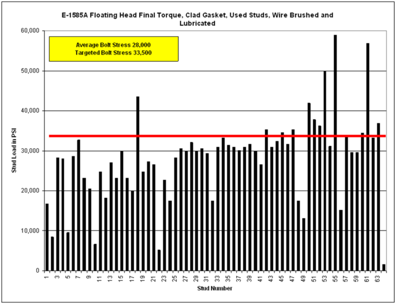
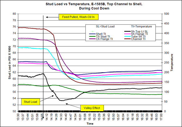
Several years ago Chevron performed a field test to investigate this issue. Among the hundreds of heat exchangers in their El Segundo refinery are the “twin” heat exchangers, E-1585A and E-1585B, identical to each other in every regard. On the day of the test they replaced the floating head gasket on each exchanger and tightened the connection. Because there isn’t enough room on the floating head, no hardened washers were used. Other than that, best practices were used; they lubed everything properly and used a calibrated clicker torque wrench on both. The only difference between E-1585A and E-1585B was the condition of the studs. New studs and nuts were used on E-1585B. On the other, E-1585A, they reused the studs after they were cleaned and wire-brushed to “like new” condition. After torquing they measured the actual stud stress – and the results are what you see on the accompanying charts.
The first chart shows the results for the used studs used in E-1585A. The table included on the chart shows that the average stud stress was 28,000-psi, which was 16.4% off from the targeted stress of 33,500-psi. But the “average” stud stress doesn’t tell the whole story, as the scatter (the difference from bolt-to-bolt) is as much as 10-to-1! Even though the studs were well cleaned and well lubricated, it was impossible to predict just how much stud load would be generated at a specific torque.
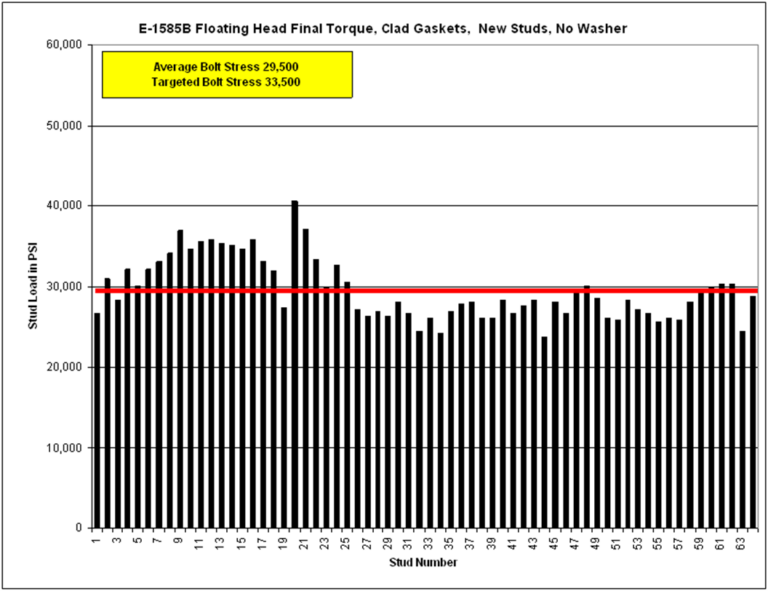
The second chart shows a greatly improved picture. The average stud load is now only 12% off from the desired load. But more importantly, the scatter has been dramatically reduced – most of the stud loads are within 10% to 15% of the average, and the amount of disparity from the lowest to the highest has been reduced by 83%!
Remember that these results were achieved without the use of hardened washers under the rotating nut. It is very likely that the use of hardened washers to reduce the frictional drag at the flange face would have reduced the scatter even more, and would have boosted the average stud load closer to the projected load. However, even though these results are not “perfect”, they are certainly “reasonable”.
Why is this critical?
Chevron has proved through years of research that in addition to using an optimal gasket type, the secret to long-term sealing in heat exchangers depends on how one deals with relaxation in the joint. In order to manage relaxation it is critical to load the gasket to achieve a high seating stress. This needs to be done reliably to a high, predetermined value.
So if an engineer determines that a gasket needs 20,000-psi seating stress to give long-term reliability – and that 600 ft-lbs torque (for example) is required to achieve that load – he has to be able to depend on the fact that when the studs are torqued to 600 ft-lbs that they will actually generate the bolt stress he anticipates.[1]
And that is the problem with used studs. Due to the almost microscopic rolling and galling on the thread surfaces, the stud no longer converts torque into stress in a predictable manner. The relationship between bolt torque and gasket load is broken. Because of this, Chevron requires the use of new studs whenever an exchanger joint is opened.
Now there are a couple exceptions to this rule – and Chevron recognizes them in its standards. First, if a stud is being tensioned (not torqued), then it’s fine to reuse them – as torque doesn’t come into play. Second, if a person is willing to run the threads on both the studs and nuts with a tap and die – thus renewing the threads – they can safely reuse the fasteners.
The argument is sometimes advanced that used studs are better than new studs because they have been work-hardened. The simple response to that argument is that work-hardening doesn’t matter. What matters is the ability of the stud to deliver a predictable load to the gasket – because that is how leak-free performance achieved.
The proof of this approach is easily seen in Chevron’s experience. In the past decade they have achieved what many considered impossible – they have eliminated exchanger leaks from their refineries. Using new studs to optimize the gasket load is an important component of the solutions employed to achieve this end.
[1] For a more complete discussion on the importance of targeting specific gasket seating stresses rather than specific stud stress, see the Tech Note titled Stud Stress or Gasket Stress? Hitting the Right Target.

The American Petroleum Institute (API) first issued its standard for Ring Joints and Ring Joint Flanges (API Specification 6B) in June of 1936. This standard (which was adopted by the American Standards Association into the 1939 edition of ASA B16e) had two different groove profiles for ring joint flanges. Flanges under 6” had a round-bottomed groove and could only use oval rings. Note that the ring did not contact on the bottom of the groove, but had a wedged contact on the tapered side of the grooves, as is still the case. The oval style of ring joint gasket was the only option for flanges under 6”. Flanges 6” and over had a flat-bottomed groove which could use either oval or octagonal ring joints.
Over the years changes were gradually introduced, so that when the 1957 edition of ASA B16.20 was published, the only groove profile was the flat-bottomed one, and octagonal ring joints were available for all sizes. This change allowed the oval or octagonal gasket to be used in new (or retrofitted) installations, whereas the oval gasket was still required in existing applications that had the earlier groove design. Undoubtedly, the fact that the octagonal gasket could not be used in some of the pre-existing flanges was a barrier to its acceptance.
Both gaskets seal by wedging tightly into the sides of the groove as they are compressed. However, the octagonal gasket has a broader sealing contact surface, as the entire 23-degree-tapered edge of the gasket ring is in contact with the mating groove face. (See drawing.)
While it is generally recognized that the octagonal ring gasket is a superior design that offers higher sealing efficiencies and reliability, oval gaskets still comprise about 90% of the market. The three factors that most likely account for this surprising fact are:
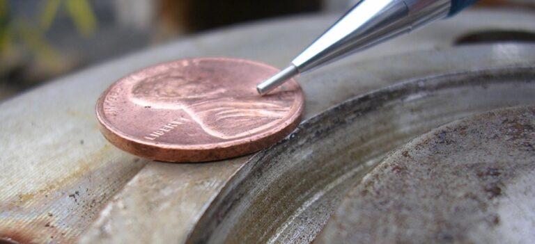
The deficiencies of the oval gasket primarily arise from its small point of contact with the flange groove. The oval cross-section generates a single-point contact ring with the flange. The narrowness of this contact results in very high seating forces. Even though the gasket is supposed to be softer than the flange material, both the gasket and the flange see some deformation as a result. This deformation continues until the gasket load is supported. While this works fine the first time – and maybe even the second and the third – eventually the flange becomes both work-hardened and deformed, making it difficult to get good conformation on the subsequent gasket. Ultimately, this increases the potential for leaks. In the following picture, the damage to the groove (“coining” deformation) is clearly visible – a result of the very high seating loads that are generated by an oval ring joint gasket.
If an incorrect gasket is installed – one that is harder than the flange – this damage to the flange is greatly exacerbated.
Since it doesn’t rely on a single-point contact ring (as the oval does), the octagonal gasket seals much more reliably than the oval gasket, and is far less sensitive to very minor flaws and imperfections in the seating surface. Having said that, manufacturers recommend that the grooves be machined to 63 RMS, whichever type is used.
The greatest advantage of the octagonal gasket is that the exact dimensions of the seating area are known, enabling the user to calculate the exact torque values that will result in a specific, targeted gasket seating stress. This allows the user to put into place more effective bolting protocols that can help – on the one hand – guarantee sufficient gasket stress to prevent leakage, while – on the other – keep from over-tightening the flange, and thereby running the risk of yielding the studs, rotating the flange, or damaging the gasket surface.
Many of our customers – in their effort to improve sealing reliability in all bolted connections – are establishing bolt-up protocols based on gasket seating stress. By switching to octagonal gaskets, these customers can now bring the entire class of ring joint flanges into the same program.
Conclusion: LGG Industrial encourages the use of octagonal ring joints.
Both of the terms “Coefficient of Friction” and “Nut Factor” are frequently used when speaking about gaskets – in particular, about the squeezing of gaskets between flanges. This is because the compression of the gasket is most often accomplished by the application of stud load that is generated by torquing a nut. So [1] turning a nut [2] stretches the stud, which is creates a [3] compressive load on the gasket.
Long-term gasket sealability is completely dependent on gasket stress, and the best sealing programs target very specific gasket stresses. But In order to be able to know if the gasket is actually being loaded to the specified target, we must be able to define the relationship between the force applied in turning the nut and the amount of stress generated in the stud.
When sliding one surface over another, the amount of force required is dependent on the frictional drag. Sliding a block of ice over a steel plate requires a lot less force than a bale of hay weighing the same amount. The ratio between the force required to move an object over another surface and the pressure between those surfaces is called the Coefficient of Friction. Since ice is far more slippery than hay, the Coefficient of Friction is much lower.
The use of an anti-seize product in bolted connections makes it easier to move one metal surface over another. The manufactures of these products experimentally determine the Coefficient of Friction imparted by that product when used between specific fastener materials. That Coefficient of Friction is often reported on the can, or in the technical bulletins for that product.
In the simple action of turning a nut onto a stud, a number of interactions take place which involve the Coefficient of Friction. The point of highest “drag” is where the nut surface turns against the stationary flange surface. Obviously, as the load on the stud increases, the pressure at this nut/flange interface increases, requiring more force to slide the one surface on the other. This force requirement is defined by the Coefficient of Friction.
Likewise, the stud and the nut both have thread surfaces that are sliding against each other. These threads are simply coiled slopes, which can be visualized as two inclined planes that are slid past each other. The Coefficient of Friction defines the amount of force required to move those planes relative to each other, but the equations that describe this interaction must take into account the pitch diameter of the threads and the helical angle of the sloped planes perpendicular to the axis of the stud.
The total torque required to achieve the needed stud stress is a sum of the torque required due to the nut/flange interface, and the torque required due to the thread interactions. And while very accurate torque values can be computed using this detailed approach, it does require a fairly complex set of equations to do so. Fortunately, there is a much simpler approach that gives very reliable results.
The Nut Factor (K) combines the thread geometry, the pitch, the friction at the nut face and the friction on the threads into one overall value. This allows us to write a very simple equation to describe the relationship between the torque on the nut and the load developed by the stud. That equation is:
Torque (ft.lb.) = Load (pounds) x Nominal Stud Size (inches) x Nut Factor / 12
While less comprehensive than equations built around the use of the Coefficient of Friction, this equation yields very good results for the standard fasteners used in the process industries.
So the torque required to generate 50,000 pounds of load on a 1-1/8” stud, using an anti-seize with a nut factor of 0.17 would be:
Torque (ft.lb.) = 50,000 (pounds) x 1.125 (inches) x 0.17 / 12 = 797 ft.lb.
The Nut Factor (which has no units) is experimentally determined by the anti-seize manufacturer, and usually falls between 0.15 and 0.20.
Both the Coefficient of Friction and the Nut Factor speak to the frictional drag in a bolted connection. However, they are not the same thing, and the terms cannot be used interchangeably. Unfortunately, these terms are often confused, and the values are used in the wrong equations, giving inaccurate results.
Both the Coefficient of Friction and the Nut Factor are determined by the manufacturer, and the end-user must make sure he understands which value is being reported.
As a general rule, the Coefficient of Friction is on the order of 0.04 LESS THAN the Nut Factor, and runs between 0.11 and 0.16.
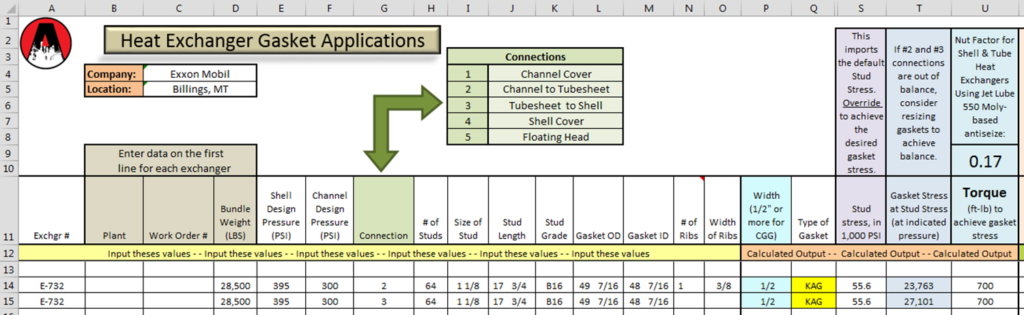
LGG Industrial uses the Nut Factor to convert torque to stress in all of our computational worksheets, including the Exchanger Gasket Workbook.
At first look, the practice of insulating flanges seems to have several clear advantages. Insulating the flanges would:
While these reasons seem compelling, they miss the central point. The most important function of a gasketed joint is to prevent leakage. When viewed in terms of this primary function, it becomes clear that the negative effects of insulating flanges outweigh the apparent benefits.
Clearly, the practice of insulating flanges tips the scale in favor of developing more leaks. So as a general rule, flanges should not be insulated.
But what about worker safety?
If the primary purpose of the proposed insulation is personnel protection, that goal can be achieved through other methods that do not impact the thermal balance of the flange. For example, Chevron uses expanded metal guards that prevent accidental contact with the flange, while still allowing free airflow.
Insulating flanges is not only going to make it more likely that you will suffer leaks, but it will also prevent you from noticing those leaks when they first occur – when they can most easily be abated.
Conclusion: It is our position at ERIKS that as a general rule, flanges should not be insulated.
Pittsburgh, Pennsylvania – ERIKS North America (ERIKS NA), a leading distributor in the industrial market, is excited to announce the promotion of Daron Steinmann to Key Industry Director of Refining & Petrochemical.
With more than 23 years of industrial experience, Daron has spent the last 20 years at ERIKS NA, initially as an Outside Sales Representative for eight years, then transitioning to a Branch Manager role for two years, and finally serving as a Product Specialist for the past five years.
When asked about his promotion, Daron said, “I’m thrilled for the opportunity to further advance the refining and petrochemical business and lead such a highly skilled team of industry professionals.”
Terry Subia, Vice President of Key Markets of ERIKS NA said, “We’re eager to see Daron continue growing our refining and petrochemical sectors. Daron’s industry experience and tenure with ERIKS NA make him a great fit for this role.”
ERIKS North America congratulates Daron Steinmann on his promotion and looks forward to his success as Key Industry Director of Refining & Petrochemical.
About ERIKS North America:
ERIKS North America, a portfolio company of LKCM Headwater Investments, is a leading distributor of fluid and material conveyance solutions for industrial customers. Our technical solutions and services keep our customers running, reduce downtime and total cost of ownership.
Contact:
Lauren Shaffer, Digital Marketing Specialist
412-925-7390
Pittsburgh, Pennsylvania – ERIKS North America (ERIKS NA), a leading distributor in the industrial market, is delighted to announce Terry Subia’s promotion to Vice President of Key Markets.
With over 35 years of sales experience in the industrial sector, Terry has been an invaluable member of the ERIKS team for the last 18 years, serving as an Industry Director for the past two years.
“We are thrilled to announce Terry’s well-deserved promotion to Vice President of Key Markets,” said Jeff Crane, CEO of ERIKS North America. “His extensive experience and expertise in the industrial market make him the perfect fit for this role. We are confident that Terry’s strong leadership skills, combined with his customer-centric approach, will guide us in achieving our growth objectives and strengthening our relationships with key customers.”
Terry will be overseeing a team of highly skilled professionals in his new role. The collaboration and expertise of this team will further bolster ERIKS NA’s capabilities in serving our valued customers.
Speaking about his promotion, Terry Subia expressed gratitude and excitement, saying, “I am honored to take on this new role in the company. I am passionate about building strong partnerships with our customers and driving organic growth. I look forward to working closely with the team to deliver exceptional value and solutions that meet the evolving needs of our customers.”
ERIKS North America congratulates Terry Subia on his well-deserved promotion and looks forward to continued success and growth under his leadership in the Vice President of Key Markets role.
About ERIKS North America:
ERIKS North America, a portfolio company of LKCM Headwater Investments, is a leading distributor of fluid and material conveyance solutions for industrial customers. Our technical solutions and services keep our customers running, reduce downtime and total cost of ownership.
Contact:
Lauren Shaffer, Digital Marketing Specialist
412-925-7390
Pittsburgh, Pennsylvania – ERIKS North America (ERIKS NA), a leading distributor of industrial solutions, is pleased to announce the appointment of Mike Deery as Vice President/General Manager of its West Region.
In this role, Mike will lead our sales team in the Western part of the United States and focus on driving growth for the organization.
Previously, Mike held the role of Vice President and General Manager for the Utility, Communications, and Transportation Business Unit at Hexagon Safety and Infrastructure where he oversaw all aspects of the business from sales, business development, technology, product development, marketing, operations, services, and installations. Mike brings a strong background in industrial supplies distribution as he has spent close to 10 years at WW Grainger leading high-performing teams in new business development, Corporate Accounts (Key Accounts), and as The Northeast US Regional Vice President. Mike also led a senior strategic selling team of National Account Managers (Key Accounts) across the USA at FleetPride, a distributor of heavy-duty truck parts.
“We are thrilled to welcome Mike to the ENA team as the Region VP/GM for the West Region,” said Jeff Crane, CEO of ERIKS North America. “His exceptional leadership skills, industry knowledge, and strategic mindset make him a valuable addition to our organization. We are confident that Mike will contribute significantly to the continued growth and success of our company.”
Commenting on his new position, Mike said, “I’m looking forward to focusing on ERIKS North America’s West Region and continuing the organization’s focus on growth and commitment to customers.”
ERIKS North America is proud to welcome Mike Deery to the team and looks forward to his contributions in his new role as Vice President/General Manager of our West Region.
About ERIKS North America:
ERIKS North America, a portfolio company of LKCM Headwater Investments, is a leading distributor of fluid and material conveyance solutions for industrial customers. Our technical solutions and services keep our customers running, reduce downtime and total cost of ownership.
Contact:
Lauren Shaffer, Digital Marketing Specialist
412-925-7390
One of the most frequent mistakes made when talking about forces is to use the words “load” and “stress” interchangeably, as if they mean the same thing. They don’t.
Simply put:
LOAD is in pounds; STRESS is in pounds per square inch.
So, there are two elephants – one in sneakers, one in stiletto high heels. Both elephants weigh the same. However, as they approach the watering hole, the elephant in stilettos starts having problems, as her heels keep sinking into the ground. Why?
Well, since they weigh the same, we know that the total amount of load (pounds) they put on the ground is exactly the same. However, the better-looking elephant (the one in the heels) is concentrating that load onto a much smaller area (pounds per square inch), so the stress on the ground is much higher where she steps.
In the world of equipment and gaskets, Load and Stress come into play with both the studs and the gaskets.
STUDS
The limit on studs is always given in terms of stress. If you look at the “Stud Data” tab on the Exchanger Gasket Workbook, you’ll find a table listing the “Yield Strength” of various stud materials. This value is a stress value, and is given in pounds per square inch, or “psi”. You’ll see that all B7 studs up to 2-1/2” diameter have a minimum yield strength (We’ll get into what that means later) of 105,000-psi.
Let’s take two studs – one 5/8”, and one 1-3/4” – and look at how they relate in terms of stress and load. Since they are both B7 material, and both are less than 2-1/2” diameter, they can both be stressed to 105,000 pounds per square inch. Imagine these studs screwed into a heavy I-beam on one end, with a special nut with a clevis on the other end, as shown in this sketch.
How much weight (Load) would we have to hang from each of the clevises in order to reach 50,000-psi stress in the stud? Clearly, the larger stud will take a lot more weight in order to get to the same stress.
The relationship between stress and load in a stud is determined by the “Tensile Stress Area” of the stud. This is the effective cross-sectional area of the stud in tension. The stress within the stud is equal to the total load on the stud divided by the tensile stress area:
Stress = Load / Tensile Stress Area
and:
Load = Stress * Tensile Stress Area
Since “load” is given in pounds, and “tensile stress area” is in square inches, the units of stress are pounds per square inch.
The Tensile Stress Area of the stud can be found on the “Stud Data” page of the Exchanger Gasket Workbook. Looking up the studs found in our example, we find that the tensile stress area of the 5/8” stud is 0.226 square inches, while the tensile stress area for the 1-3/4” stud is 2.081 square inches. From the equations above we can compute:
For the 5/8” stud: 50,000 * 0.226 = 11,300 pounds
For the 1-3/4” stud: 50,000 * 2.081 = 104,050 pounds
So, we would have to hang almost 10 times as much weight from the larger stud just to have the same stress as the smaller stud. Stated differently, the stress is the same, but the load is higher because the cross-sectional area of the stud is so much greater.
In considering gasket applications, we almost always need to be thinking in terms of gasket stress – the compression in pounds per square inch on the gasket. However, the gasket stress always comes from the stud stress. To get from the one to the other, we need to go through the following steps:
This simple conversion from stud stress to stud load, and back from stud load to gasket stress becomes second nature as we work with gasket sealing issues.
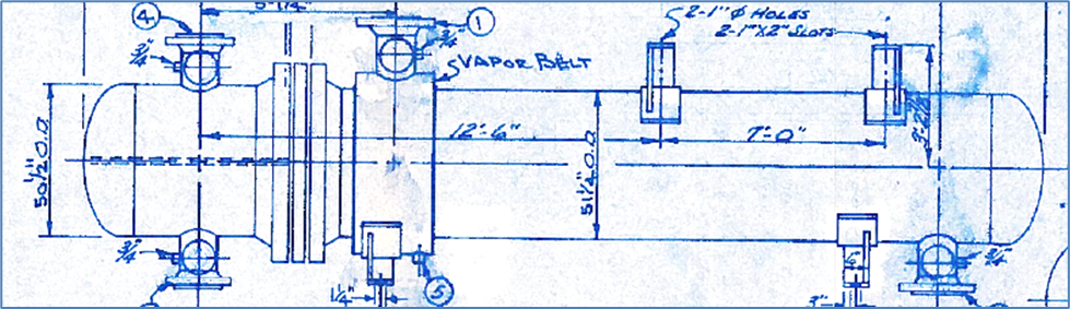
Background: This hot feed / effluent heat exchanger has a history of leaking that extends back 10 years and includes clamping and leak-sealing by outside contractors, as well as changing the gasket styles on at least two occasions to “upgraded” styles suggested by manufacturers. The most recent change in 2010 was to a kamprofile gasket with Mica/Graphite/Mica sealing elements. At that time, the flange surfaces were inspected, the new gaskets were installed, and the flange was tightened per refinery procedures. However the Tubesheet-to-Shell joint developed a small leak shortly after start up, and a steam ring was installed.
This is a TEMA type BEU exchanger with only one joint (channel – tubesheet – shell), with two gaskets and one common set of studs. The stud material was originally B7, but has been upgraded to B16. The joint utilizes 64, 1-1/8” studs that were torqued to a final value of 700ft.lb.
Analysis: The information provided by the client was loaded into the Exchanger Gasket Workbook to analyze the gasket seating stress under operational conditions. Barring defective components – whether flanges or gaskets – heat exchangers leak due to low gasket seating stress. For this reason we always look first at the gasket seating stress at full operating pressure. Regardless of the “Y” value of the gasket, we have found that reliable sealing of graphite-faced gaskets requires a gasket stress between 10,000 and 40,000-psi. If possible, we work to achieve a gasket stress in the 20,000 to 25,000-psi range. Not only is that tight enough to provide a great seal at start up, but it is also tight enough to offset the inevitable relaxation found in heat exchanger joints.
Given the leakage history on this unit, we anticipated a low gasket stress. However, the gaskets on this exchanger were loaded to nearly ideal levels. (The final page of this analysis is a snapshot of the Exchanger Gasket Workbook.) The question that must be resolved is how an exchanger that is designed to deliver 25,000-psi gasket stress can begin leaking shortly after start up. What factors might have contributed (historically) to the low-stress conditions that allowed leakage?
A full review of the equipment drawings and the related documents led us to two significant factors related to the equipment and gasket
designs, and two additional factors that were assembly related. Chief among these contributing factors was the threaded tubesheet.
The equipment drawings show (below) that the 64 holes in the tubesheet are threaded for the 1-1/8” studs.
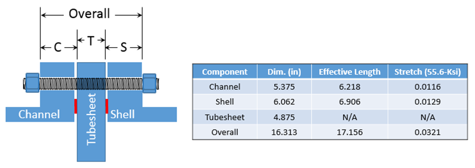
As currently configured, the portion of the stud on the channel side acts independently of the portion of the stud on the shell side. The total amount of stretch in the stud is 0.0245”. However, if the tubesheet were drilled out, the full length of the stud would stretch under tension, providing 0.0321” of stretch – a 31% increase! For a flange that leaks habitually, this is a huge improvement of stud response.
It is interesting to note that the gasket stress drops more than the stud stress, because of the effect of the hydrostatic end-load on the joint. The table below summarizes the resultant gasket stress if there were a relaxation of 0.006” on each side of the tubesheet. (This is not an excessive estimate.) Each side is considered independently, because they are isolated from each other by the threaded tube sheet. Notice that the stud stretch and
stud stress are directly related, because the stud is a linear spring. But the gasket stress drops far more, because of the stud stress that is diverted to offset the hydrostatic end force in the joint.
The table below models the same scenario – a relaxation of 0.006” on each side of the tubesheet, for a total of 0.012” relaxation. However, in this case the tubesheet has been drilled out, allowing the full stretch of the stud to interact with both gaskets. Compared to the above chart, the percentage of stud stretch and stud stress drops far less, and the resultant gasket stresses are improved 30 – 50%!
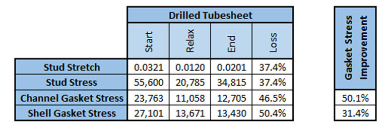
Clearly, the short studs amplify the loss of gasket stress when relaxation occurs. Because of these dynamics, ERIKS recommends drilling out all threaded tubesheets. The purpose of the stud is to stretch to maintain gasket stress, and threaded tubesheets limit the ability of the stud to do so. We have clients who are now routinely drilling out tubesheets whenever they come across them.
If a refiner feels that they need to retain the ability to hold the Tubesheet-to-Shell joint tight while removing the Channel, they can do this with only one stud in four. So even if it is felt that drilling all the holes is not prudent, drilling three out of four holes would still improve the stud load on the gasket, while preserving the ability to remove the Channel independently.
Summary: While a simple numerical analysis seemed to indicate that there was adequate seating stress on the gaskets to prevent leakage, the fact that leakage was regularly occurring indicated underlying problems that were resulting in low gasket stress.
Beside issues related to the specific style of gasket utilized, the re-use of studs, and the lack of a post start-up retorque, the greatest contributor to the loss of gasket stress was the threaded tubesheet; which, in this case predated any changes in the gasket style. This conclusion is in line with field observations of leaks that are related to threaded tubesheets.
Recommendation: Drill out all 64 holes in the threaded tubesheet to allow the stud the maximum stretch with the calculated stud stress. As a bonus, this will make assembly easier, as the stud does not have to be tightened from both ends.